15 Results
View results:
Sort by:

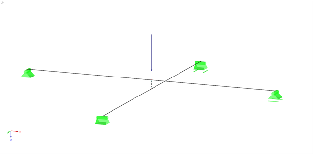
This article describes how a flat slab of a residential building is modeled in RFEM 6 and designed according to Eurocode 2. The plate is 24 cm thick and is supported by 45/45/300 cm columns at distances of 6.75 m in both the X and Y directions (Image 1). The columns are modeled as elastic nodal supports by determining the spring stiffness based on the boundary conditions (Image 2). C35/45 concrete and B 500 S (A) reinforcing steel are selected as the materials for the design.
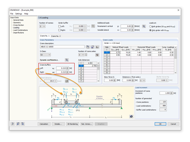
In the event of converting or extending a hall, the building owner may want to add a second or third crane to an existing crane runway. Since the original design usually does not consider other cranes, a common solution is to design a minimum distance between the cranes. This is done via the crane technology settings.

For uniformly distributed loading according to EN 1992‑1‑1 (Eurocode 2), the design section for the shear reinforcement can be placed at the distance d from the front edge of the support. Thus for the shear reinforcement, the applied shear force is reduced to VEd,red. To analyze the maximum design shear resistance VRd,max, however, the total shear force is applied.
Until now, if you wanted to determine the centroid of a rectangle, it was necessary to define a line from one corner point to the diagonally opposite point. You obtained the centroid by dividing this line. In RFEM 5 and RSTAB 8, you now have the possibility to create a node between two points. Thus, it is sufficient to select the corner points; then you can determine the distance in absolute or relative values.

For cross‑laminated structures with large spans, downstand beams or hybrid structures are often used. They can be modeled in RFEM 5 by using surfaces and member cross‑sections. In both structural systems, curved downstand beams are also possible without any problems. In the case of the curved surface, the member is always appropriately generated by means of the automatic member eccentricity with the thickness distance of the surface and the member. The downstand beam can also be connected flexibly by means of a line release.
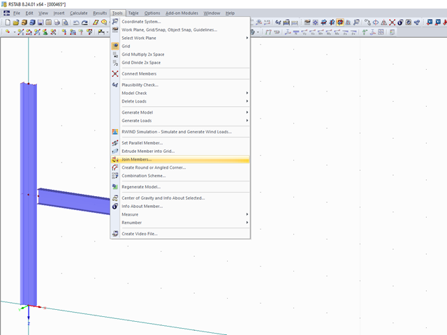
To join free members to the members located within a certain maximum distance, use the "Join members" function.
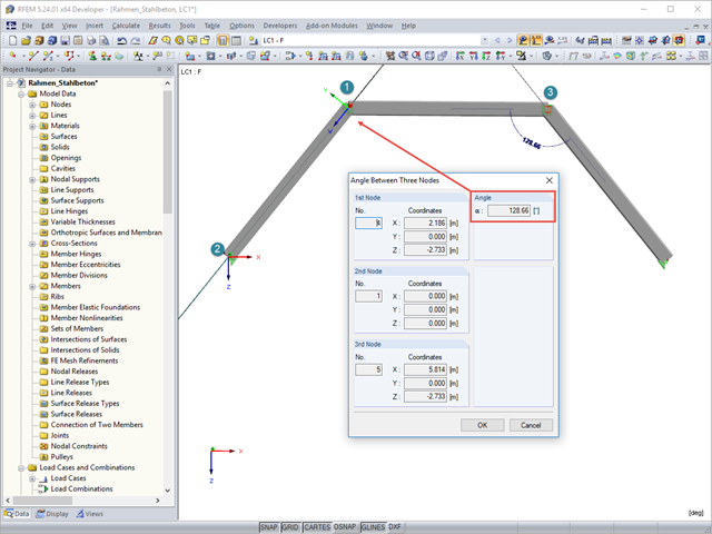
To determine the distance between two nodes or the angle between two objects without using the dimensioning function, you can simply use the "Measure" option on the "Tools" menu. Here, you can also choose between various measure functions.
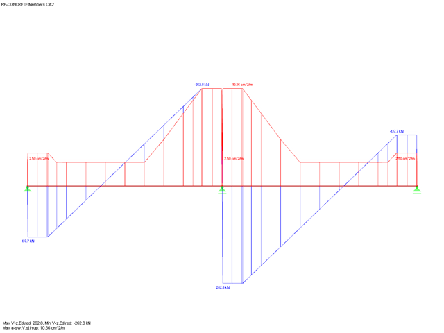
When performing shear force design in RF-CONCRETE Members and CONCRETE, you can reduce the acting shear force Vz according to EN 1992-1-1. The following article describes the reduction of the concentrated loads close to the support and the shear force design at the distance d from the support face for a uniform load.
From time to time, two intersecting beams overlap at a short distance. Such a structure raises the question, with regard to the modeling, of how it is possible to consider a contact with force transmission under compression between the two beams, while the contact under tension (for example, in case of a lifting top beam) should fail.
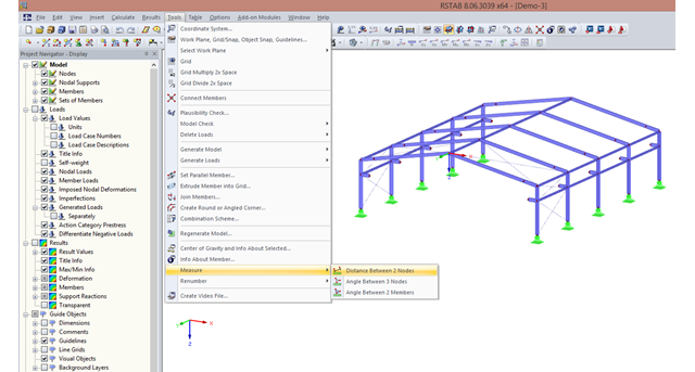
The "Measure" function available in the "Tools" menu allows you to measure distances and angles.
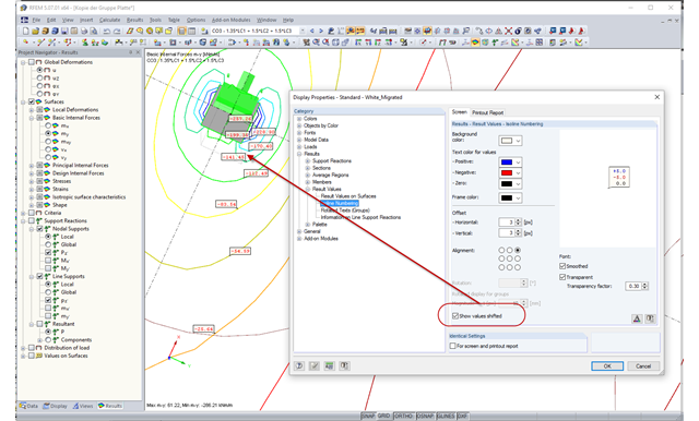
In the case of very small distances between isolines, the labels often overlap, which makes the result documentation difficult. As of RFEM version 5.06, you can select a shifted arrangement of the isoline labels in the Display Properties dialog box. By selecting the "Show values shifted" option, you can easily avoid overlapping the result values in many cases.
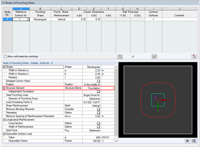
The RF‑PUNCH Pro add‑on module allows you to perform the punching shear design of floor slabs and foundation plates according to EN 1992‑1‑1. In the case of a floor slab, the basic control perimeter is applied according to 6.4.2 (1), EN 1992‑1‑1 [1] at a distance of 2d from the loaded area.
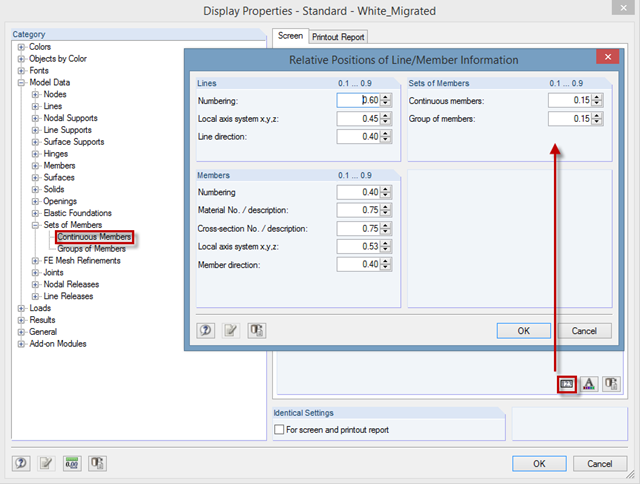
In RFEM and RSTAB, you can arrange the labeling of lines, members, and sets of members in a user‑defined way. To do this, open the dialog box in "Display Properties", where you can define the position of the information about the relative distance from the member start.
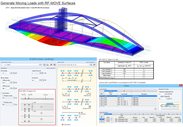
Moving loads can be generated easily with RF‑MOVE Surfaces. A library is available with load models as defined in Eurocode 1, Part 2. The input of step size, offsets at start and end, and the distance to a reference line make it possible for the user to generate user‑defined load models and influence the number of load cases generated. RF‑MOVE Surfaces generates load cases and, optionally, a result combination as an envelope of all results.
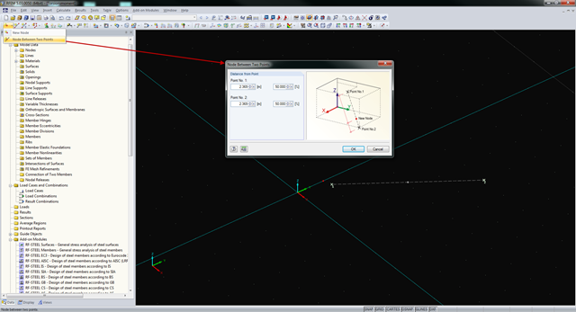
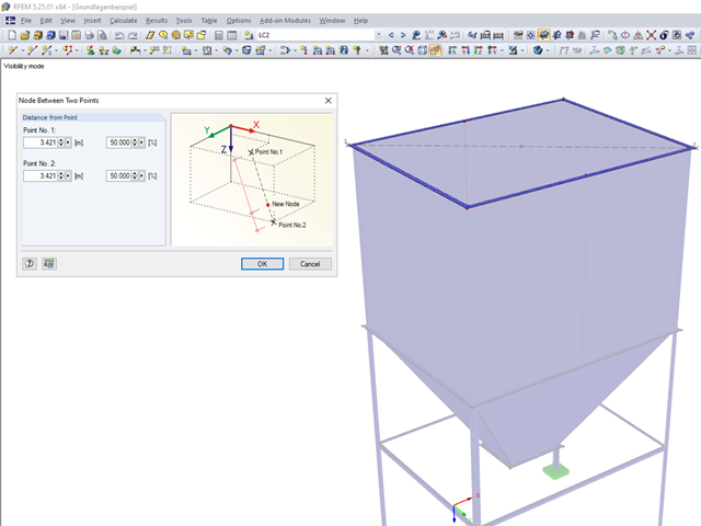
In RFEM and RSTAB, you can create nodes not only by means of coordinates, but also by means of existing nodes. You can use the "Node Between Two Points" function to create a node located on an imaginary line connecting two nodes. You can enter the distance as a percentage or according to the relative lengths.